
Page 134 - Çevre Şehir İklim İngilizce - Sayı 4
P. 134
Seismic Isolation in Earthquake -
Resistant Structural Design for Resilient Cities
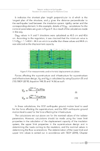
b indicates the shortest plan length perpendicular to d which is the
longest plan of the structure, and y gives the distance perpendicular to
the earthquake load between the insulation system rigidity center and the
corresponding element. In this example, details of D TM calculations for the
nominal parameters are given in Figure 9. As a result of the calculations made
in this way,
D TM values in X and Y directions were calculated as 40.5 cm and 40.6
cm. According to the regulation, it was checked that the minimum value is
1.1×D M = 1.1×40.4 = 44.4 cm which is smaller than these values and 44.4 cm
was selected as the displacement capacity.
Figure 9. Plan measurements used in the total displacement calculation
Forces affecting the superstructure and infrastructure for superstructure
and infrastructure design, V D and V is calculated by using Equation (9) and
M
(10) (TBDY (2018), Equation 14B.35 and 14.36) as such:
In these calculations, the DD2 earthquake ground motion level is used
for the force affecting the superstructure, and the DD1 earthquake ground
motion level is used for the force affecting the infrastructure.
The calculations set out above are for the nominal values of the isolator
parameters. However, calculations should be made using the lower limit
properties in the calculation of the displacement capacity of the insulation
system, the upper limit properties in the superstructure design and in
determining the loads coming to the insulators, and the nominal values in
determining the floor accelerations. The determination of the lower limit and
upper limit values is carried out in accordance with TBDY (2018), Chapter
Year 2 / Issue 4 / July 2023 123